
Gears
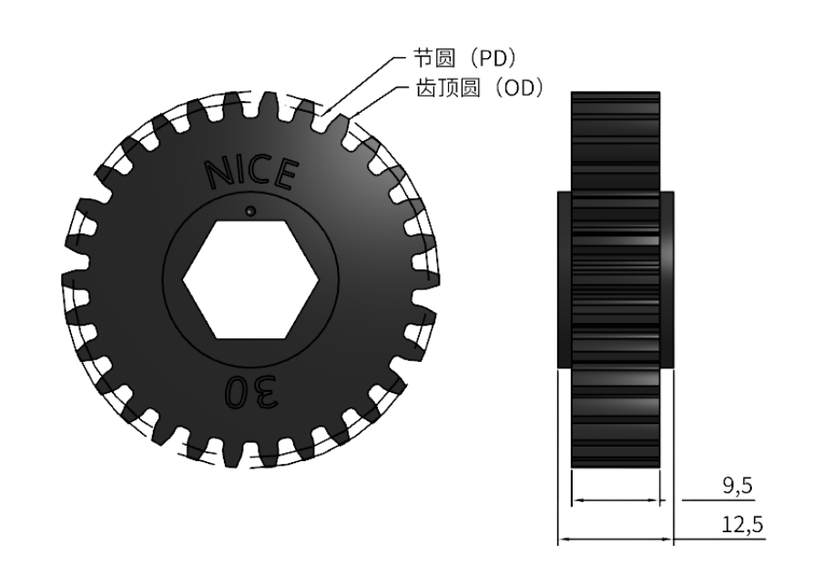
Gears transfer rotation from one shaft to another. By pairing different tooth counts, you can trade output speed for torque:
- For more torque, drive a larger gear with a smaller one. Output speed decreases while torque increases.
- For more speed, drive a smaller gear with a larger one. Output speed increases while torque decreases.
Gear drives are especially useful when:
- Shafts are close together: power needs to travel only a short distance.
- Space is limited: a substantial speed reduction must fit in a compact mechanism.
- Direction must reverse: the two shafts need to rotate in opposite directions.
| Name | Symbol | Description | Formula |
|---|---|---|---|
| Tooth count | T | Total number of teeth on the gear | |
| Face width | FW | Width of the toothed portion | 9.5mm across the range |
| Overall width | OW | Total width of the gear | 12.5mm across the range |
| Outside diameter | OD | Diameter measured over the tooth tips | [(T + 2) / DP] inch |
| Diametral pitch (DP) | DP | Tooth count per inch of pitch diameter; specifies the gear tooth size | T / PD |
| Pitch diameter | PD | Diameter of the theoretical circle that rolls against the mating gear's pitch circle | (T / DP) inch |
| Gear ratio | i | Ratio of the two gear tooth counts | T_driver / T_driven |
Gear Ratio
Section titled “Gear Ratio”The ratio between two meshing gears determines output speed and torque. With equal tooth counts, the speed and torque remain the same in the ideal case.
Speed Reduction: More Torque at Lower Speed
Section titled “Speed Reduction: More Torque at Lower Speed”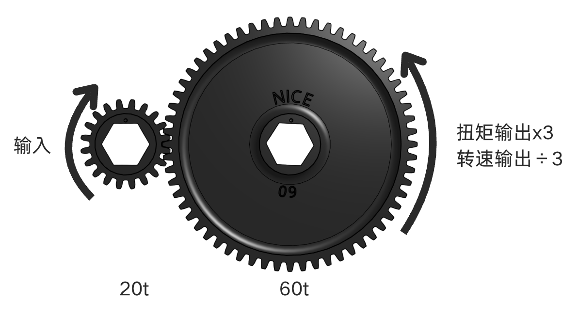
Use this when: the mechanism needs more torque.
Arrangement: a small driving gear turns a larger driven gear.
Example: a 20-tooth gear drives a 60-tooth gear.
- Driving-to-driven tooth ratio: 1:3
- Output speed is ⅓ of the input speed
- Output torque is 3 times the input torque, ignoring losses
Speed Increase: Higher Speed at Lower Torque
Section titled “Speed Increase: Higher Speed at Lower Torque”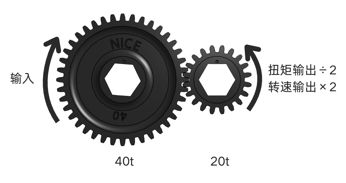
Use this when: the mechanism needs a higher maximum speed.
Arrangement: a large driving gear turns a smaller driven gear.
Example: a 40-tooth gear drives a 20-tooth gear.
- Driving-to-driven tooth ratio: 2:1
- Output speed is 2 times the input speed
- Output torque is ½ of the input torque, ignoring losses
Rotation Direction
Section titled “Rotation Direction”Gears also change the direction of rotation.
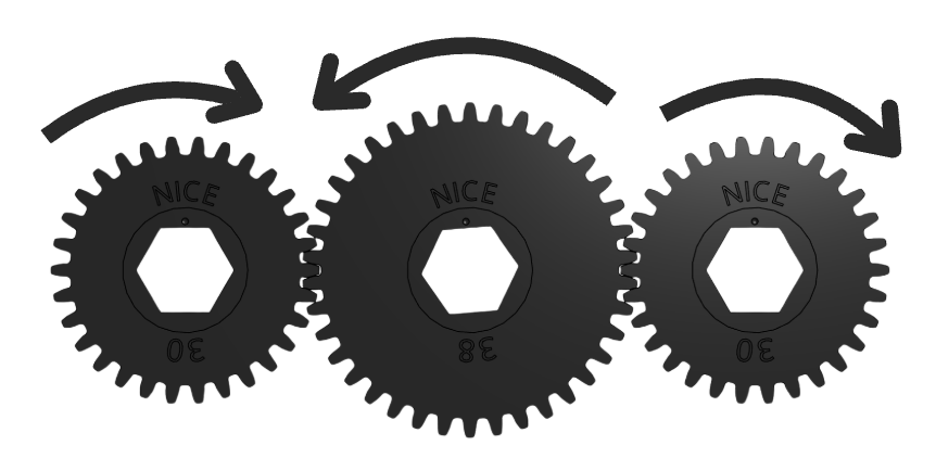
- Two gears: the input and output rotate in opposite directions.
- Three gears: the input and output rotate in the same direction.
Center Distance
Section titled “Center Distance”Center distance is the distance between the two shaft centers:
Here, C is center distance, D₁ and D₂ are the two pitch diameters, and a is the center-distance allowance. Use the same units throughout.
Center-Distance Allowance
Section titled “Center-Distance Allowance”In practice, adding a small allowance (0.03mm–0.05mm) to the theoretical center distance can:
- Reduce gear wear
- Help the gears run smoothly
- Introduce slightly more backlash between the teeth
Suggested allowances:
- Close fit: +0.000mm (theoretical center distance, tightest mesh)
- Running clearance: +0.03mm to +0.05mm (recommended for smoother operation)
Changing Ratios at a Fixed Center Distance
Section titled “Changing Ratios at a Fixed Center Distance”For example:
| Driving gear | Driven gear | Total tooth count | Gear ratio | Center distance |
|---|---|---|---|---|
| 20t | 60t | 80t | 1:3 | 50.8mm (2") |
| 32t | 48t | 80t | 1:1.5 | 50.8mm (2") |
Both gear pairs above have the same center distance (50.8mm), but different ratios.
NICE Aluminum Gears
Section titled “NICE Aluminum Gears”All NICE gears share these specifications:
- Diametral pitch: 20DP
- Pressure angle: 14.5°
- Face width: 9.5mm
This makes it easy to change gear combinations to tune performance. Keep the total tooth count unchanged when retaining the same shaft spacing.
Solid-Web Gears
Section titled “Solid-Web Gears”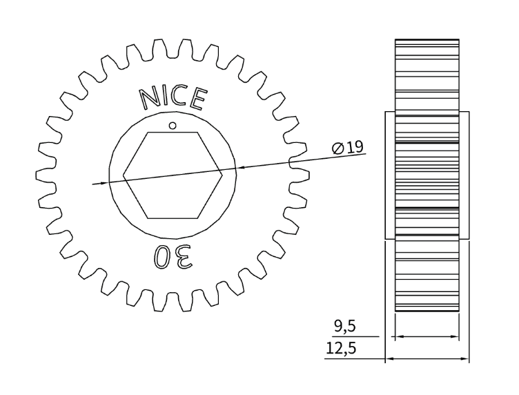
- ½″ hex bore, compatible with standard ½” hex and rounded-hex shafts
- 7075-T6 aluminum alloy with black hard anodizing
- High strength and wear resistance
- 9.5mm face width
| SKU | Weight | Tooth count | Drawing | CAD model | Onshape |
|---|---|---|---|---|---|
| NICE-02-01-001 | 10g | 20t | PDFNICE-D-02-01-01.pdf | STEPNICE-02-01-001.step | |
| NICE-02-01-002 | 13g | 22t | PDFNICE-D-02-01-01.pdf | STEPNICE-02-01-002.step | |
| NICE-02-01-003 | 16g | 24t | PDFNICE-D-02-01-01.pdf | STEPNICE-02-01-003.step | |
| NICE-02-01-004 | 20g | 26t | PDFNICE-D-02-01-01.pdf | STEPNICE-02-01-004.step | |
| NICE-02-01-005 | 23g | 28t | PDFNICE-D-02-01-01.pdf | STEPNICE-02-01-005.step | |
| NICE-02-01-006 | 27g | 30t | PDFNICE-D-02-01-01.pdf | STEPNICE-02-01-006.step | |
| NICE-02-01-007 | 31g | 32t | PDFNICE-D-02-01-01.pdf | STEPNICE-02-01-007.step | |
| NICE-02-01-008 | 25g | 34t | PDFNICE-D-02-01-01.pdf | STEPNICE-02-01-008.step | |
| NICE-02-01-009 | 40g | 36t | PDFNICE-D-02-01-01.pdf | STEPNICE-02-01-009.step | |
| NICE-02-01-010 | 45g | 38t | PDFNICE-D-02-01-01.pdf | STEPNICE-02-01-010.step |
Pocketed Gears
Section titled “Pocketed Gears”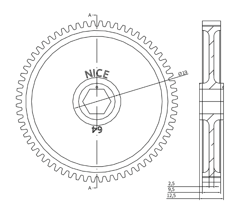
Pocketed versions are available for larger gears with 40 teeth and above, reducing weight while retaining strength.
- ½″ hex bore, compatible with standard ½” hex and rounded-hex shafts
- 7075-T6 aluminum alloy with black hard anodizing
- 9.5mm face width
- Weight-relief pockets with a minimum web thickness of 2.5mm
- Lower weight with reliable strength